09/05/2018
Homebrew Z80 computer: Step 1
I've been wanting to build a homebrew computer, start with something "simple" and work my way up. Since I'm already mired in vintage computers I began thinking about 8-bit processors of the past like the MOS 6502 and the Zilog Z80. I’ve seen a number of contemporary projects centered around these chips, and after some research and consideration, I decided to use the Z80. Furthermore, I would only use new parts that can be purchased from mouser.com today.
One of the first milestones I set out for myself was to build up a breadboard and a front panel, reminiscent of an Altair 8800 or IMSAI 8080. I'd consider this a successful test if I could use it to add two numbers. Something to get my feet wet, and show the basic operation of the CPU. I finally hit that mark this week.
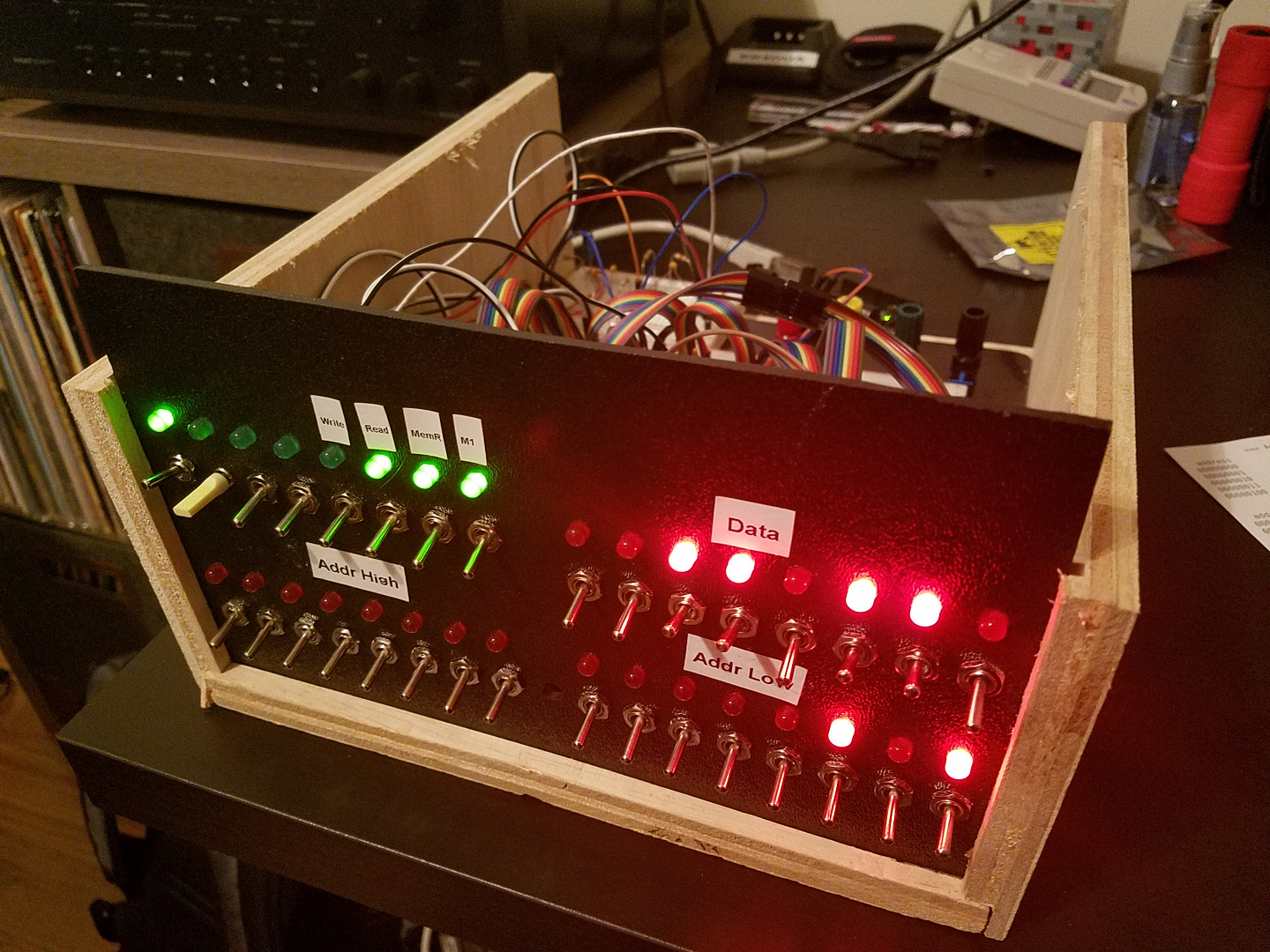
The traditional Z80 comes in a 40 pin DIP chip and has 8 data pins, 16 address pins, and other timing/control lines. On my front panel, I basically just connected a switch and LED to all the address and data pins, then LEDs for various outputs, and a switch to trigger a single clock pulse from a monostable 555 timer.
With everything wired up, I was ready to flip switches and run my program to add two numbers. Looking through the Z80's instruction set, I planned out a sequence that loads a number into the accumulator, then adds another number to it. For "output" I decided to use an instruction that loads the contents of the accumulator to some address on no importance.
assembly  =>	hex =>	binary
ld a,n		3E	00111110
		02	00000010
add n		C6	11000110
		03	00000011
ld (bc),a	02	00000010
Of course, to actually use this with my front panel, we need the binary from the actual byte sequence represented by the assembly code (shown above). I can flip switches on and off, representing 1s and 0s, and then step the clock signal to the CPU. In this example we're adding the numbers 2 and 3, just so I can quickly verify that 5 or 00000101 is our desired result.
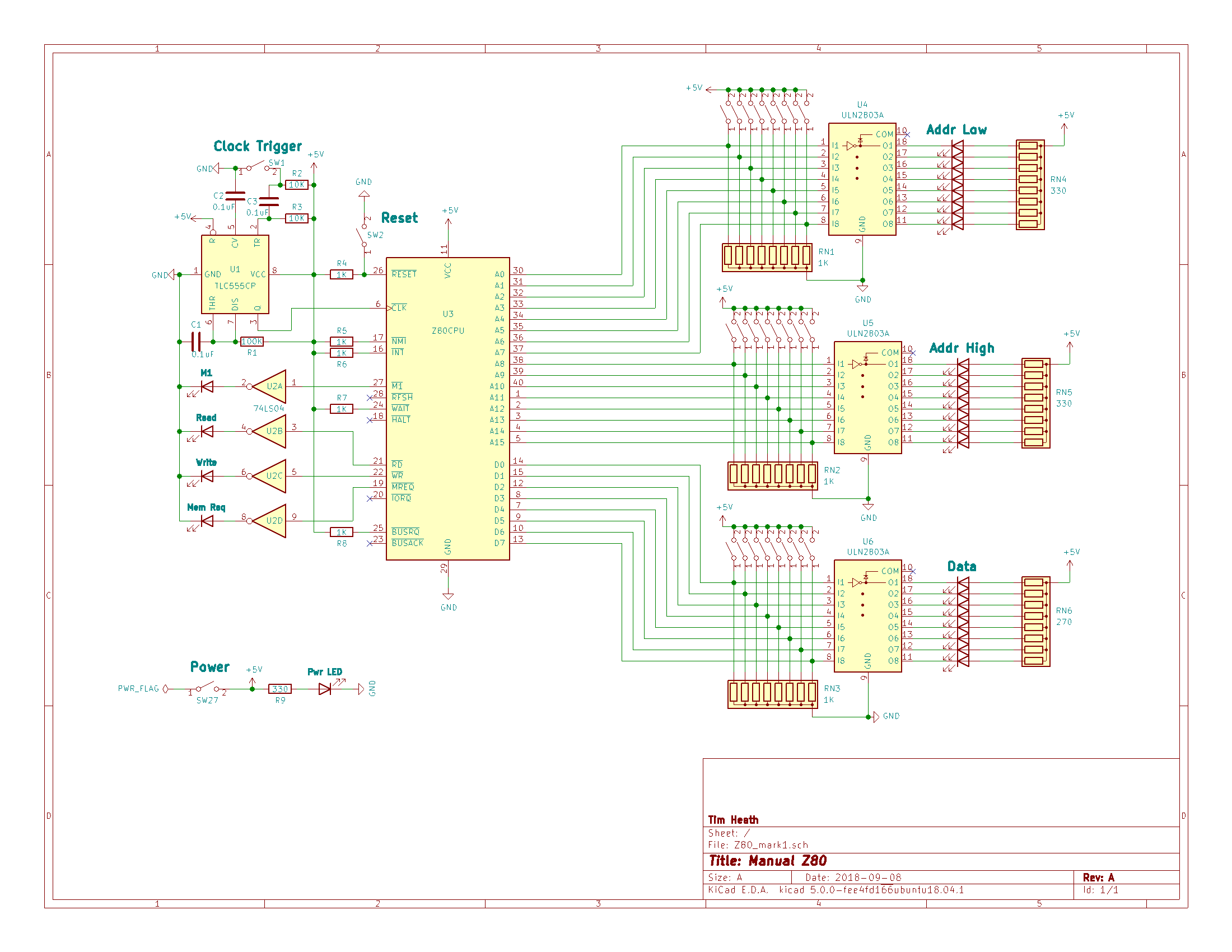
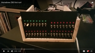
I'm quite pleased with how this turned out, and plan to add things like memory and a serial interface before moving on to custom PCBs and more complext I/O. For now, you can see my schematics and more photos below or click the image above for video of operation.